ako neko ima semu za bord komp, konkretno za astru g 2.0 turbo
potrebno mi je da vidim na sta se sve vezuje pa da znam da li da se upustam u to ili ne

| Opel Team Serbia https://opelteamserbia.com/forum/ |
|
| potrebna sema za bord komp astra g https://opelteamserbia.com/forum/viewtopic.php?f=146&t=28596 |
Stranica 1 od 1 |
| Autoru: | chile [ 18 Feb 2014 23:46 ] |
| Tema posta: | potrebna sema za bord komp astra g |
ako neko ima semu za bord komp, konkretno za astru g 2.0 turbo potrebno mi je da vidim na sta se sve vezuje pa da znam da li da se upustam u to ili ne
|
|
| Autoru: | bobale [ 19 Feb 2014 00:40 ] |
| Tema posta: | Re: potrebna sema za bord komp astra g |
Gledao sam po TISu, nije uopšte komplikovano ako hoćeš samo potrošnju da meriš. Nemam trenutno instaliran TIS da ti iskopiram šemu, ali naćiće se neko. Čudi me da ti to nemaš instalirano već? Google Translateuj ga, interesantan članak http://www.motor-talk.de/blogs/-tbmod?t ... %C3%BCsten |
|
| Autoru: | chile [ 19 Feb 2014 00:46 ] |
| Tema posta: | Re: potrebna sema za bord komp astra g |
bas listam po netu i najvise podataka sam nasao po ceskim forumima kod njih je to bas masovno prebacivanje sa tid na mid, cak i prave bord kompove cena 76-78e u zavisnosti od boje displeja |
|
| Autoru: | bobale [ 19 Feb 2014 00:48 ] |
| Tema posta: | Re: potrebna sema za bord komp astra g |
Ja našo jeftinije |
|
| Autoru: | lemi84 [ 19 Feb 2014 00:50 ] |
| Tema posta: | Re: potrebna sema za bord komp astra g |
Bordcomputer (MID) im Astra G nachrüsten Es gibt grob gesagt 2 Möglichkeiten für die BC Nachrüstung die Basic-Version dient hierbei der Arbeitserleichterung um schnell und einfach die wesentlichen BC-Funktionen zur Verfügung zu haben Version 1 - Basic Aktive Funktionen: - Reichweite - Durchschnittsgeschwindigkeit - Momentanverbrauch - Durchschnittsverbrauch - Stoppuhr - Prüfung der Bremslichtsicherung Version 2 – Volles Paket (Wie ab Werk auch) Aktive Funktionen: - Reichweite - Durchschnittsgeschwindigkeit - Momentanverbrauch - Durchschnittsverbrauch - Stoppuhr - Prüfung der Bremslichtsicherung - Scheibenwasserkontrolle - Kühlwasserkontrolle - Überwachung des Bremsbelags vorn - Glühlampenkontrolle (Abblend-, Rück-, Bremslicht) - Ölstandkontrolle Nötig ist das Basic Paket damit der BC überhaupt funktioniert, das volle Paket sollten nur die nachrüsten, die mit der Elektrik des Fahrzeugs vertraut sind... Es können aber logischerweise auch nur einzelne Sensoren nachgerüstet werden z.B. nur Scheibenwasserkontrolle Anmerkung: Die zahlen in den Klammern sind die Katalognr. aus dem Lieferprogramm des Herstellers Die Bezeichnungen der Steckverbindungen sind aus Schaltplänen des Fahrzeugs entnommen Paket «Basic» benötigte Teile: 1. Multi Info Display MID (Foto 1, 2) Neupreis: 728,52 € nicht erschrecken gebraucht bekommt ihr das MID für ca. 150 € es muss auch nicht genau dieses eine MID Display sein es gab mehrere verschiedene (siehe auch FAQ Übersicht Display Arten) 2. Lenkstockschalter mit Bedienknöpfen für BC (mit Heckwischer Funktion: 12 41 135 ohne Heckwischer Funktion: 12 41 134) (Foto 3) Neupreis: 79,90 € und 77,34 € gebraucht für ca. 15 € zu haben 3. ca. 5m Kabel 0,5 mm² 4. MID Stecker 32 Pin (Foto 4). Bild zeigt den Original Stecker wie er am Kabelbaum ab Werk (mit Bordcomputer) zu finden ist. Stecker und Pins gibt es bei Opel grundsätzlich nicht einzeln...(wenn doch dann nur als extrem überteuerte Reparatursätze) fehlende Stecker sowie passende Pins gibt es aber günstig als Neuware über mich zu beziehen Multi Info Display (MID): 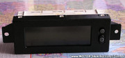 Multi Info Display (MID): 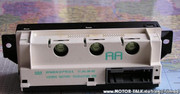 Lenkstockhebel mit BC Knöpfen: 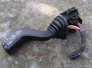 32-poliger MID Stecker: 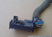 Anmerkung: Es existieren viele Varianten des MID z.B. mit Zuheizer oder mit Telefonunterstützung (Carphone MID) Diese Anleitung handelt von einem "normalen" MID ohne jegliche Zusätze, denn dies funktioniert immer und überall... aber auch die anderen MID Display's sollten sich ohne Probleme nachrüsten lassen. (Bitte Programmierung beachten!) Kommen wir nun zum Einbau: Das TID (Tripple Info Display) könnt ihr getrost rausschmeißen, denn es kann absolut gar nichts außer die 3 Sachen anzeigen, was es ja auch macht. Aber der Stecker davon besitzt 12 Kabel die unbedingt nötig sind bei der Nachrüstung des MID. 12-poliger TID Stecker: 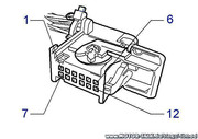 32-poliger MID Stecker: 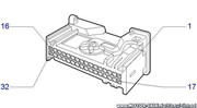 Diese 12 Kabel sind aus dem Stecker des TID zu entnehmen und in den 32 pol Stecker einzusetzen, dies ist möglich da die Pins absolut identisch sind. Man nehme beide Stecker auseinander indem man: 1. den Kabelbinder durchschneide 2. den Schwarzen inneren Einsatz mit den Pins aus dem Gehäuse entferne indem man die Widerhacken mit einem kleinen Schraubendreher wegdrücke und dabei am Kabelstrang ziehen muss. Jetzt die Pins entnehmen. Am einfachsten geht es mit einer Nadel, man drücke die Widerhacken und ziehe an jedem einzelnen Kabel. Die Pins werden nach folgendem Schema wieder eingefügt: Die Rot markierten Kabel sind vom TID vorhanden und müssen nur von einem Stecker in den anderen übertragen werden. Das blaue Feld erklären das Verbrauchssignal in einer extra Tabelle weiter unten. Pin am MID -Stecker # Kabelfarbe # Funktion # Pin am TID -Stecker # Anschluss an # Einbauort falls vorhanden 1 # Braun # Masse # 6 # Vorhanden # Stecker TID 2 # Blauweiß # Außentemperatur # 5 # Vorhanden # Stecker TID 3 # Blau # Außentemperatur # 7 # Vorhanden # Stecker TID 4 # Schwarz # Sicherung 1.13 ab MJ2002 3.13 # 1# Vorhanden # Stecker TID 5 # Rot # Sicherung 3.34 ab MJ 2002 1.34 # 3 #Vorhanden # Stecker TID 6 # Grün # Drehzahlmesser # Instrumentenstecker (Tacho) Pin 20 7 # Graugelb # Multitimer/MUT # 4 # Vorhanden # Stecker TID 8 # Rotweiß # Radio/EMP (Radio Infos,Datum etc..) # 2 # Vorhanden # Stecker TID 9 # Braunrot # Radio/EMP # 10 # Vorhanden # Stecker TID 10 # Braungrau/grün # CD -Wechsler/Autotelefon # 12 # Vorhanden # Stecker TID 11 # Braunschwarz/weiß # CD - Wechsler/Autotelefon # 11 # Vorhanden # Stecker TID 12 # Blaurot # Wegstreckengeber/WEG # 9 # Vorhanden # Stecker TID 13 # Braungrün # Sensor Ölstand # Kontrollschalter Ölstand oder Masse # Neu legen! 14 # Braunweiß # Diagnosestecker # 8 # Vorhanden # Stecker TID 15 # Schwarzgelb # Bremslichtschalter # Bremslichtschalter direkt Pin 2 bei zweipoligem oder Pin 3 bei 4poligem Schalter 16 # Schwarz # Sicherung 1.38/Bremslicht ab MJ 2002 3.38 # Sicherung 38 oder Bremslichtschalter direkt Pin 1 bei zweipoligem Schalter oder Pin 4 bei 4 poligem Schalter # Sicherungskasten 17 # Weißgrün # Glühlampenkontrolle # Glühlampenkontrolle Pin 1 oder Masse # Neu legen! 18 # Schwarzgelb # Glühlampenkontrolle # Glühlampenkontrolle Pin 2 oder offen! # Neu legen! 19 # Gelbrot # Sensor Bremsbelag # Kontrollschalter Bremsbelag oder Masse # Neu legen! 20 # Braunblau # Sensor Kühlflüssigkeit # Kontrollschalter Kühlmittel oder Masse # Neu legen! 21 # Unwichtig war mal für Automatikgetriebe vorgesehen bis MJ 2000 22 # Braungelb # Sensor Waschflüssigkeit # Kontrollschalter Waschflüssigkeit oder Masse # Neu legen! 23 # Braunweiß # Lenkstockchalter MID / A # Zum Lenkstockschalter weiß # Neu legen! 24 # Braunrot # Lenkstockschalter MID / D # Zum Lenkstockschalter rot # Neu legen! 25 # Nicht belegt 26 # Blauschwarz # Tankgeber # Instrumentenstecker# Pin 25 # Instrument 27 # Schwarzbraun # Verbrauchsignal(Steuergerät) # Motorabhängig # Alle Motoren 28 # Braun/Grau nur bei MJ 2001-2002# Bremslichtschalter# Pin 2# bei allen Motoren ausser Y20DTL/Y20DTH/X16XEL und Z20LET 29# Grau/Grün # Nur bei Zuheizer # X6 Pin 8 30# Schwarz/Grau # Nur bei Zuheizer # X6 Pin 9 31 # Blau # Kühlwassertemperatur / INS # Instrumentenstecker (Tacho) Pin 28 32 # Nur bei Zuheizer # X2 Pin 14 Verbrauchsignale am Motorsteuergerät: Z12XE # Stecker X 79 # Pin 52 X12XE # Stecker X56 # Pin 16 Z14XE / Z16XE + XEP / Z16SE # Stecker X 71 # Pin 47 Z14XEP # Stecker X52 # Pin 59 Z16YNG # Stecker X141 # Pin 47 X16SZR # Stecker X 55 # Pin 9 X14XE / X16XEL # Stecker X 53 # Pin 21 Z18XE und XEL # Stecker X 57 # Pin 20 X18XE1 und X20XEV # Stecker X 57 # Pin 5 Z20LET # Stecker X 125 # Pin 52 Z22SE # Stecker X 77 # Pin 8 Y17DT/DIT # Stecker X 73 # Pin 47 Y20DTL + DTH / X20DTL / X17DTL # Stecker X 59 # Pin 29 Y20DTH/Y22DTR mit PSG 16 # Stecker X 93 # Pin 26 Z17DT # Stecker X129 # Pin 12 auch hierfür ist meistens ein Pin für den Stecker am Motorsteuergerät notwendig diesen bekommt ihr unter anderem auch bei mir (sofern vorhanden) je nach Motor unterschiedlich Anmerkung zum Bremslichtschalter X-Motoren immer 2 polig verbaut bei Tempomat auch der 4 polige bei Z-Motoren immer grundsätzlich der 4 polige zum 4 poligen: bei den ersten Baujahren Betreff Modelljahre bis 98.5 waren Pin 3 und 4 andersherum belegt ! die Beschreibung oben bezieht sich auf alle ab MJ99 Stecker Instrument (Tacho): 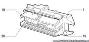 Stecker Instrument (Tacho): 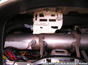 Gegenstecker vom Lenkstockhebel: 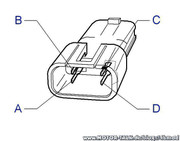 Anmerkung: Wenn der Gegenstecker nicht aufzutreiben war, dann muss man den Lenkstockschalter direkt ohne Stecker anlöten. Das dritte Anschlusskabel (braun) des Lenkstockhebels geht auf Masse Paket «Voll» benötigte Teile: 1. Paket «Basic» 2. Glühlampenkontrolle (62 38 078) Neupreis: 80,47 € gebraucht für ca. 20 € zu haben idealerweise gleich mit Gegenstecker 3. Kühlwasserbehälter mit Loch für Kühlwassersensor (13 04 223) (Foto 17) Neupreis: 31,48 € 4. Kühlwassersensor (13 04 729) (Foto 16) Neupreis: 23,64 € 5. Bremsbelagsensor (2 St.) (12 38 442 oder 62 35 674) Neupreis ein Satz (2 Stück): 20,94 € 6. Ölstandsensor (Kat. Nr. Motorabhängig) mit Dichtung (Kat. Nr. Sensorabhängig) Neupreis schwankt zwischen 84 € und 110 € 7. Wischwassersensor (12 38 401) mit Dichtung (12 38 821) (Foto 16) Neupreis Sensor: 23,22 € Dichtung: 1,85 € 8. Ölwanne mit Loch für Ölstandsensor (Kat. Nr. Motorabhängig) Neupreis schwankt zwischen ca. 180 € und 230 € 9. Bohrmaschine und Bohrer mit 19mm Durchmesser 10. 8m Kabel 1,5 mm² 11. 10m Kabel 0,75 mm² 12. Multimeter Wischwasser- und Kühlwassersensor: 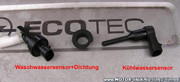 Kühlwasserbehälter mit Loch für Sensor: 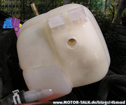 Der Anschluss der ganzen Sensoren ist simpel, jeder Sensor hat 2 Kabel wobei einer auf Masse gelegt wird und der andere zum 32 Poligen Stecker vom MID gezogen wird...dabei gibt es eine Besonderheit bei den Bremsbelagsensoren, diese weiden nämlich in Reihe geschaltet, d.h. Pin 1 vom linken Sensor wird am MID angeschlossen Pin 2 geht rüber zu Pin 1 am rechten und Pin2 vom rechten geht an Masse. Dabei benötigt man noch die ganzen Gegenstecker für die Sensoren die jedoch auf Schrottplätzen etc. zu finden sind, da es ganz einfache Stecker sind die auch wo anders verbaut wurden. Wischwassersensor: Wischwasserbehälter mit Loch für Sensor gibt es nicht. Alle werden verschlossen ausgeliefert. Aber jeder Behälter hat unten rechts eine kleine Vertiefung, die für den Sensor gedacht ist. Hier kommt der Bohrer ins Spiel. Man muss ein 19mm loch an dieser Stelle in den Behälter bohren. ACHTUNG: Das loch muß exakt 19mm im Durchmesser haben. ansonsten ist es entweder undicht oder ihr bekommt den Sensor nicht hinein. Wischwasserbehälter: 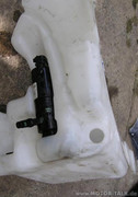 Glühlampenkontrolle: Diese ist dafür gedacht, einen Fehler zu melden, falls eine der überwachten Lampen defekt ist. Es werden die Abblend-, Rück- und Bremslichtlampen überwacht, indem das Steuergerät in die Zuleitung zwischen der Sicherung und der einzelnen Lampen geschaltet ist. Das Signal wird dann ans MID weitergeleitet und dort angezeigt. Es sollte ein zentraler Ort gesucht werden, von dem man alle Leitungen gut erreichen kann (z.B. Da wo das normalerweise sitzt, hinter dem Beifahrerairbag) Falls auch dieses Steuergerät nicht vorhanden ist, müssen am Stecker der Pins 17 auf Masse gelegt werden, der Pin 18 bleibt offen! (wichtig) Steuergerät für Glühlampencontrolle (CC): 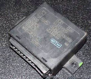 Stecker Glühlampenkontrolle: 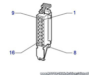 Hier die Belegung für die Glühlampenkontrolle: Pin # Funktion # Farbe 1 # an Pin 17 MID # Weiß-grün 2 # an Pin 18 MID # Schwarz-gelb 3 # ----- # ----- 4 # ----- # ----- 5 # Masse # Braun 6 # Hinter Sicherung Abblendlicht links # Gelb 7 # Hinter Sicherung Abblendlicht rechts # Gelb 8 # an Lampe Bremslicht links # Schwarz-gelb 9 # an Lampe Rücklicht links # Grau-schwarz 10 # an Lampe Rücklicht rechts # Grau-rot 11 # Hinter Sicherung Rücklicht links # Grau-schwarz 12 # Hinter Bremslichtschalter # Schwarzgelb 13 # Hinter Sicherung Rücklicht rechts # Grau-rot 14 # an Lampe Abblendlicht links # Gelb 15 # an Lampe Abblendlicht rechts # Gelb 16 # an Lampe Bremslicht rechts # Schwarz-gelb Stromlaufplan Glühlampenkontrolle: 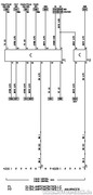 Kabelführung im Astra G: 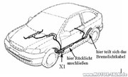 Vorher/Nachher Glühlampenkontrolle:  Danach alles anstecken Strom einschalten und ausprobieren. Wenn ihr alles richtig gemacht habt sollte das MID jetzt funktionieren. Startet mal den Motor und achtet auf den Verbrauch, die Durchschnittgeschwindigkeit und so weiter.. zeigt im Normalfall absolut merkwürdige Werte an, oder nur "Programm" wenn es Neu ist. Da das MID (meistens jedenfalls) vorher in einem Astra gesessen hat, der nicht unbedingt denselben Motor und Steuergerät hatte, ist das MID auch genau auf diese Kombination programmiert. Damit ihr genau wisst, welchen Code ihr im Moment habt, drückt die Set und die Reset Taste zusammen gleichzeitig für ca. 3 sec, dann seht ihr die Codenummer, Softwareversion und die Impulse pro km. Also, auf zum freundlichen Opelhändler und diesen bitten, das MID mit dem richtigen Programmcode zu versehen. Viel Spaß mit dem Bordcomputer Pixeltest: Ölstand Prüfen: 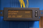 Waschwasser Stand:  Bremsbelag: 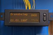 Fahrlicht Rücklicht:  Bremslicht Sicherung:  Kühlmittel Stand: 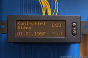 EDIT: bobale vec ostavio link, moze brisanje mog posta |
|
| Autoru: | chile [ 19 Feb 2014 01:10 ] |
| Tema posta: | Re: potrebna sema za bord komp astra g |
hvala mile neka stoji ima i slikica bobale, http://veramon.czweb.org/en_pp_cenik_opel_mid.html ovde ovako pise evo i na engleskom Installation of the On-Board computer Astra G (MID) An onboard computer is different depending on whether the vehicle was originally installed MID (32-pin connector), or only TID (12-pin connector). In the case of exchange of the MID is not necessary to install any additional wiring is performed only change the display. In the case of exchange of the TID is necessary to install the necessary wires that are on a volume not to TID display . Before installation, disconnect the car battery while the car battery is disconnected and the involvement of the vehicle must not be any person !!! Removing the center console: - Remove the radio and storage space (the drawer under the car radio) - Remove ashtray and remove the cover of a car cigarette lighter - Allow the screws under the cover of a car ashtray and lighter - Remove the metal shaft radio (on the back is screw) - Cut to the car stereo connectors, including the antenna connector - Allow the screws on the sides, where they found the shaft radio - Disconnect the control air-conditioning (2 clips at the top and bottom 2 clips) - Pull switch to remove the directional warning lights Now we no longer cover the entire center console holds the upper metal clip, making it stronger by pulling out and then pull out. - Push out the plug warning light - Disconnect connector from the display TID Removing the panel board instruments: - Take off two covers at the bottom of the flight instrument - Allow four screws (2 below and 2 above) - Push out the plastic cover on-board instruments - Allow the screws that hold the board device (2 below) - Disconnect connector (top left of the lever is plastic) - Remove the panel board instruments - Remove the connector cable assembly from the cradle To remove the connector to the cable assembly from the holder, it is necessary to squeeze plastic holder at the bottom left downwards. Connector beam can then be easily pulled to the left out Removing control: - Pull the two plastic screw covers on the steering wheel (it is necessary to turn the steering wheel) - Unscrew the screws underneath these covers - Towards the top remove the top cover of the proceedings - Unscrew the screw from the bottom of the lower housing management - Top two screws to allow the lower housing management - Remove the bottom cover management - Control lever to slide out after pressing the two plastic latches on the sides The extension wires into the engine compartment: The engine compartment can be reached in several ways, namely: - Around the Bowden control opening bonnet - Rubber grommet over the pedals - Around the internal heating pipes Some vehicles are already wire from the control unit can be located on the wiring harness connector, which is led from the engine bay into the interior of the vehicle. It's a good idea to verify the installation of a new campaign to save wire. However, the connection of the connector X2, where the driver is taken out from the control unit is quite complicated, because the connector is poorly accessible. In the case of wire drawing looks best stretch wire around the brake cable control for opening the bonnet or even better around the pipe internal heat, which is slightly permeable foam. The extension is appropriate to use a heavier wire, which at the end sands and then puncture the rubber (foam), the outer casing (pipe) passes into the engine compartment. In the engine compartment to put the best car driver ”goose neck“ and attach the wires to the other route via pull-down strap. Connecting the BC (for cars with 12- pin connector): The original connector of tidu is designed to be inserted directly into the onboard computer module. The 32-pin connector on the module board computer connect other wires needed, depending on what all will be installed. Accordingly, you can also order the appropriate harness. For a basic BC just plug the following section: 32-pin Connector on BC Connect to: Basic connection ----------------------------------------------------------------------------------------------------------------- Pin n. 1 (GND) The control lever, brown wire Pin n. 6 (RPM) The instruments onboard, Pin n. 20, green wire Pin n. 23 (Button RESet) The control lever, white wire Pin n. 24 (Button SET) The control lever, red wire Pin n. 26 (Fuel) The instruments onboard, Pin n. 25, blue-black wire Pin n. 27 (ECU) According to table the engine control unit For some control functions ----------------------------------------------------------------------------------------------------------------- Pin n. 15 (switch brake) Switch brake (12V when you press the brake pedal) Pin n. 16 (switch brake) Switch brake (12V after turning the key in the ignition) Pin n. 31 (coolant indicator) The instruments onboard, Pin n. 28, blue wire The remaining control functions ----------------------------------------------------------------------------------------------------------------- Pin n. 13 Oil Level Pin n. 17 Check Control, Pin n. 1 Pin n. 18 Check Control, Pin n. 2 Pin n. 19 Brake pads Pin n. 20 Coolant Level Pin n. 22 Washer Level Mechanically attached BC is just like the original MID or TID. Before tightening the screws and bolts PP vystĹ™edĂme tighten. Cabling to prepare, covers insulating tape, or put in the "goose neck" and keep the margin for easy handling and insertion into the connector module BC after stretching and all connections. Wires leading to the devices should be plugged into some sleeves. Wire connection for devices with self-tapping perform connections or soldering and then " dragging" shrink sleeve. Wires to the control lever can be connected directly, but in cases where the levers it can cause complications. Therefore, it is preferable to use a 3-pin connector. Original counterpart to the control lever, however, is looking bad. The engine management system: Engine Type Type ECU: PIN to the ECU X12XE / 1998 Motronic 1.5.5 PIN n. 16 X14XE / X16XEL Multec PIN n. 21 / X53 X16SZR Multec PIN n. 9 X18XE / X20XEV Simtec PIN n. 5 X17DTL / X20DTL EDC 15M PIN n. 29 Y17DTL / Y20DTH EDC 15M PIN n. 29 Y16XE / Z16XE Multec PIN n. 47 / X71 Z18XE Simtec PIN n. 20 / X57 Z22SE Multec PIN n. 8 / X77 Z12XE Motronic 1.5.5 PIN n. 52 / X79 Y14XE / Z16SE Multec PIN n. 47 / X71 Y20DTL / Y20DTH EDC (PSG5) PIN n. 29 / X59 Y20DTH / Y22DTR EDC (PSG16) PIN n. 26 / X93 Z20LET Motronic PIN n. 52 / X79 Y17DT PIN n. 47 / X73 Z16XEP Multec PIN n. 47 / X71 Z17DT (Z17DTL) PIN ÄŤ. 12 / X129 Z14XE Multec PIN n. 47 / X71 Wire color, if it is installed it is brown. The listing pin engine control unit based on the documentation I have to install the MID, which was listed by production models 2002nd It is likely that they will pay for subsequent years of production, but it is necessary to check the mail. documentation for the model of the vehicle. Engine control unit X12XE since 1999 have reportedly preparing for the onboard computer. In this case the wire connected directly to the fuel injection valve, but you must use the isolating optocoupler. The install somewhere in the engine compartment. If better alternatives will already be a pin on the control unit will be assembled and connected it to a conductor. In this case, terminate and connect the wire to the wire from pin-board computer module. The remaining wire that was originally connected to the insulated pin and leave it unconnected. Vehicles in the 2000/2001 production year around are usually fitted with a pin and the wire is terminated at connector X2. Vehicles made later, the driver usually do. It seems, began to investigate every meter cable. If the pin connector on the control unit is not equipped at all, it should be added. A suitable option appears to be the pin of the 15-pin serial connector / female. Top of the middle line, because the pin is longer. The cable is to be soldered to pin. Then drag the pin shrink tubing. But we do not shrink tubing over the pin because the pin is a small band and drop through the tubing This crest would have prevented us from inserting the pin into the connector (see photo). Before inserting the pin hole should be cleansed of such small bit of silicon, silicon which pull out. With proper installation procedure, the risk of damage to a minimum. Outlets control units are usually resistant to short circuits to the frame of the vehicle, but the damage could send them a direct connection board voltage, ie voltage battery. The driver of the PA module is connected internally to 12V 10K resistor, so that in case of bad connection leads to another, thanks to the ECU pin low power threaten damage to the outlet of the control unit. Input circuit-board computer module for input from the control unit includes a ”flip-flop schmitt“ Hysteresis with a relatively large, so it is resistant to interference. However, it is possible to use shielded cable, which could be further eliminate possible interference. When using shielded cable, shielded only involved in the connector module on-board computer. The controllers do not attach the shield. Connecting climate control: The climate control will use a miniature relay is closing his practice simulates switch button on the control panel. Colors of wires and turn on the connector can vary by type. Before connecting the wires is necessary to check their accuracy. Top with a voltmeter / ohmmeter. The drivers for the climate control has to be 12V when you press the button climate control. After removing the connector and measuring the ohmmeter to the connector must be between the pins by pressing the right buttons for climate control fault. Air Behr: Pin 11 red wire 4 mm Pin 4 purple wire 0.5 mm Air Delphi: Connector X65 / 5 black wire 4 mm Connector X66 / 2 black / green wire 0.5 mm If the outlet for the climate control is available (the proceedings are dealt with by other means), it is necessary to remove control panel with buttons and connect directly to the relay switch, which switches the air conditioning. After connecting all cables to connect to the onboard computer module connector from the original TID, plug the wire from the control unit from the onboard instruments, the operating lever and can proceed to completion. On-board computer module assembly increasing the depth of the screen, so you must cut a hole in a paper cover for the display, which would otherwise be the module on-board computer and the screen pushed and could not be assembled center console. jos samo da neko ubaci semu tid , mid i onda ce biti kompletno a sta je GlĂĽhlampenkontrolle: na svapskom uputstvu? |
|
| Autoru: | lemi84 [ 19 Feb 2014 01:24 ] |
| Tema posta: | Re: potrebna sema za bord komp astra g |
provjera sijalica |
|
| Autoru: | chile [ 19 Feb 2014 01:25 ] |
| Tema posta: | Re: potrebna sema za bord komp astra g |
totalno nepotrebno |
|
| Autoru: | bobale [ 19 Feb 2014 22:28 ] |
| Tema posta: | Re: potrebna sema za bord komp astra g |
Chile, a što ne uzmeš ovaj? http://veramon.czweb.org/en_pp_cenik_opel.html Upola je jeftinije, a opet završava poso Ako si zainteresovan daj da napravimo neku kombinaciju i da uzmemo obojica po jedan, biće nam jeftinija poštarina. |
|
| Autoru: | chile [ 20 Feb 2014 00:50 ] |
| Tema posta: | Re: potrebna sema za bord komp astra g |
video sam nije losa ponuda, ali uzecu od calibrice fabricki troredni perfektan je nijedan piksel mu ne fali 
|
|
| Autoru: | Plavac [ 20 Feb 2014 18:41 ] |
| Tema posta: | Re: potrebna sema za bord komp astra g |
Da li neko zna kako bi kod mene mogao da se aktivira BC,na slikama je koji je i sta prikazuje kada se pritisne bc 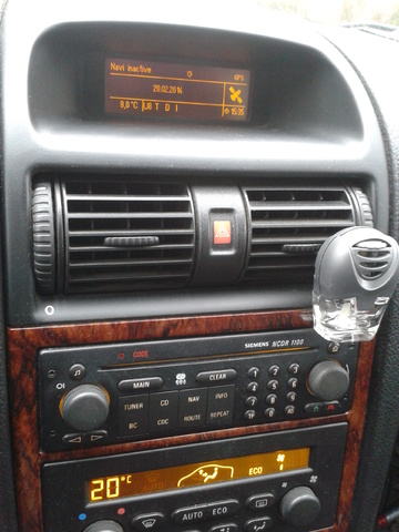 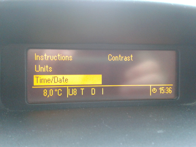
|
|
| Autoru: | Nezki [ 20 Feb 2014 18:44 ] |
| Tema posta: | Re: potrebna sema za bord komp astra g |
jesi probao da kliknes na ovo BC dugme |
|
| Autoru: | Plavac [ 20 Feb 2014 18:49 ] |
| Tema posta: | Re: potrebna sema za bord komp astra g |
Kad se klikne ispisuje to sto sam slikao |
|
| Autoru: | Nezki [ 20 Feb 2014 19:42 ] |
| Tema posta: | Re: potrebna sema za bord komp astra g |
a jel imaš na desnoj ručici dugmiće? tu se menja šta bord pokazuje na običnom bordu |
|
| Autoru: | Plavac [ 20 Feb 2014 20:49 ] |
| Tema posta: | Re: potrebna sema za bord komp astra g |
Nemam,samo ovo na NCDR 1100 ko ima ovaj uredjaj fabrički da li ima i na ručici dugmiće ili upravlja sa samog uredjaja? |
|
| Stranica 1 od 1 | Sva vremena su u UTC + 1 sat [ DST ] |
| Powered by phpBB® Forum Software © phpBB Group http://www.phpbb.com/ |
|